Santa delivered Gary Nicholson a 3D printer for Christmas and he’s been having fun designing and printing various bits and pieces.
I’ve been using:
- https://www.thingiverse.com/ to get existing 3D designs
- https://www.tinkercad.com/ to make my own designs
- https://ultimaker.com/software/ultimaker-cura to slice the designs
- https://octoprint.org/ on a Raspberry Pi 4 to control the printer
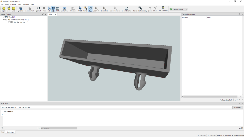
As the 3D models are STL files, which FME supports, I’ve found FME Data Inspector to be useful to have a quick look at the models before loading them into Cura. Here is a replacement bracket for a slat bed I made viewed in Data inspector.
But as FME can write 3D STL files I’m interested to see how much I can use FME with the 3D printer. This series of posts will detail the steps along the way to a fully automated process where a user can go to an FME Flow App web page and enter the names of two people who are having some sort of competition and select a score between 5 and 10 that the winner needs to get to. FME will then:
- Dynamically create an STL file,
- Email a preview of the model to the user,
- Have Cura slice it to a GCODE file,
- Upload the GCODE to OctoPrint,
- Start the print,
- Monitor the print and email the user that it is done, with a photo of the final print.
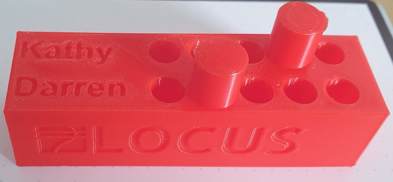
This is what the final 3D print will look like for Kathy and Darren who play first to 5 games of cribbage. Stand by for the next post which will explain how an FME workspace can dynamically create the 3D STL file, with two users names and the number of holes as input parameters. It will also emboss the Locus logo and website on two sides of the scorer.
FME and 3D Printing, Pt I – Creating the 3D model
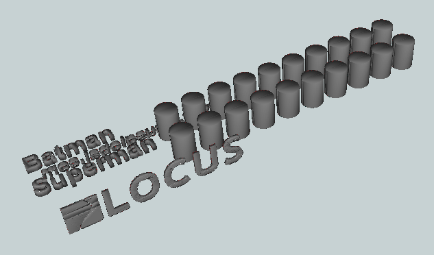
The model that we want to end up with (Batman and Superman with 10 holes each):
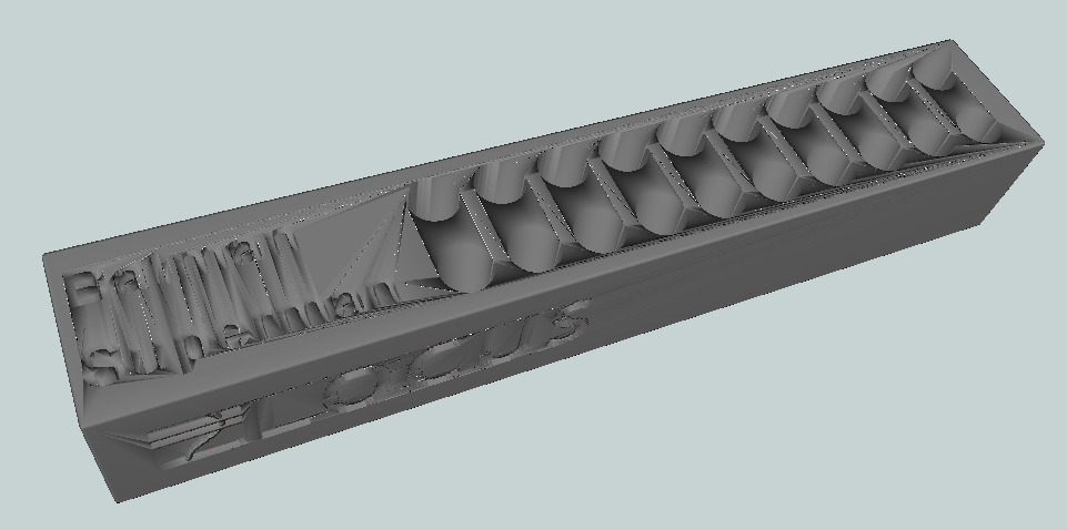
It’s basically a box, with slightly rounded corners:
With bits cut (clipped) out of it:
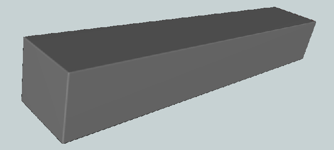
The first step then is to create a box. The depth and height are fixed at 22mm and 19mm respectively, but the length is dynamic and is determined by the length of the longest name and by the number of holes wanted.
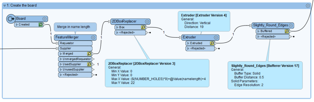
We’ll get to length of the name later but the length of the box is defined by the Max X Value of the 2DBoxReplacer and is set to the name length plus the number of holes times 9mm (distance between hole centres) plus an extra 4mm. The width (Max Y Value) is set to 22mm. This could be made dynamic as well if you wanted to support more than two names, or just one name if you have no-one to play with.
After the 2D size of the box is created with the 2DBoxReplacer it is extruder by 19mm vertically to create the 3D box. This then goes through a Bufferer with a Buffer Distance of 0.5mm to slightly round the corners. That is all that is required to create the main box, so it now goes to the Clippee input port of a Clipper so the other features can be clipped from it.
The features that are created to clip the box are:
- Names
- Peg holes
- Locus logo
- Locus Global website
Names
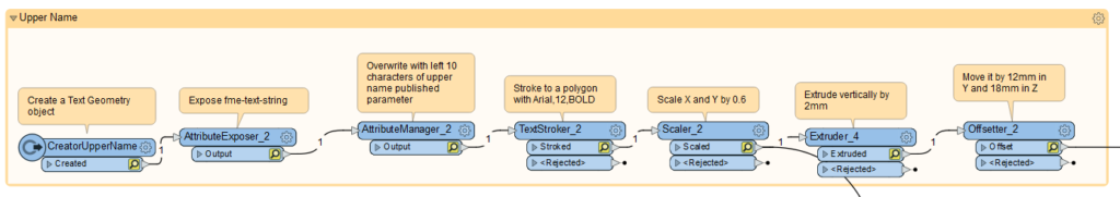
Creation of a name starts with a Creator making a Text Geometry feature. The fme_text_string attribute is exposed and overwritten with the left ten characters of the name. This is to limit the length of the resulting model. A TextStroker changes the feature to a polygon, which is scaled slightly (60%) and then extruded vertically by 2mm. For the upper name it is moved 12mm in the Y axis and 18mm in the Z axis with an Offsetter. For the lower name this is 1.5mm and 18mm respectively. Both name features are passed to the Clipper input port of the Clipper transformer where they will get removed from the box.
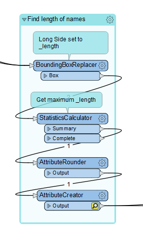
Both names are sent to a BoundingBoxReplacer which gets their longest side and a StatisticsCalculator get the maximum value. This is what is passed to the box creation process mentioned above through the FeatureMerger.
Peg Holes
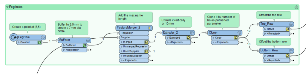
The holes for the pegs start off as a single point which is then buffered by 3.5mm to create a circle of 7mm diameter. This is then extruded vertically by 10mm to create a cylinder. It is cloned by the number of times request in the published parameter and two copies of each clone are sent to Offsetters, one for the top row and one for the bottom row.
The X Offset for both rows is @Value(_copynum)*9+@Value(namelength) where _copynum is coming from the Cloner and namelength is also coming from the maximum name length calculation via a FeatureMerger.
The Y Offset for the upper row is 11.5mm and for the lower row it is 0.5mm. The Z Offset for all the holes is 10mm. All the holes also get passed as Clipper features to the Clipper transformer.
Locus Logo
The Locus logo starts off as a PNG file which is read in and then passed to a RasterToPolygonCoercer which results in the above. Some tidying up is done to remove smaller polygons and areas are dissolved resulting in:
This is extruder by 2mm then 3DRotated by 90 degrees on the X Axis (to stand it up), then it is offset by X=4mm, Y=0.2mm, Z=16mm. It is then also passed as a Clipper feature.
Locus Website
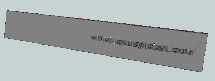
At the back of the scorer is the Locus website URL. This is created the same as the names except it has a 3DRotator of 90 degrees on the X Axis followed by a 3DRotator of 180 degrees in the Z Axis just before the Offsetter of X=65mm, Y=21mm and Z=6mm. It is also sent as a Clipper feature.
STL File
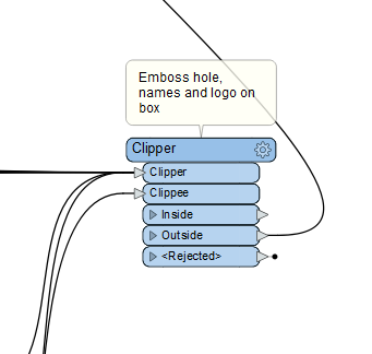
The Clipper transformer has one Clippee feature, the box, and multiple Clipper features, the names, the peg holes, the URL and the logo. It is the Outside port that gives us the 3D model we are after and that can go directly to an STL writer.
Up Next
Be sure to come back to the Locus Blog for the next chapter in this series | FME and 3D Printing, Pt II – Making a FME Flow web app. For any enquires related to FME and 3D printing please contact Locus.